
Also, he decided to put an accumulator pack and a microUSB-accumulator-load-slot into it.
WARNING: This project is freaking expensive and only for enthusiasts. It is a nice thing but it's very costly. I bet you can never sell it for the price below, which is:
--> more than 300 CHF and counting...
This is the device we are talking about, in exactly that color (but this images are stolen from the internet because we started making pictures after the start of modding.)

And here is an image of the back, for your consideration:

Here is what we got to build into the case:
http://opcoa.st/JGdT7

Also he got a Li-Ion-Accumulator-pack, a loading-chipset hardware breakout and a miniUSB-plug.
 |
| Accumulator, USB-and-loader-breakout and Everdrive. |
First a view from the workplace: In front you see a not-yet-functional 3D-printer (software issues). The GameBoy workplace is just beneath it, you cannot see it.
 |
| Workplace |
 |
| All the needed parts. |
Ok, first he opened that the GBC and the Everdrive. For the GameBoy you need a special screwdriver with three 3 "corners". (NOT a triangle! It's like a normal screwdriver but...triple.)
He soldered a cable to each pin of the GameBoy-hardware and put in the Accumulator and loading-stuff.
 |
| First try with cables. |
 |
| Soldering the cables together. |
After that he soldered it to the Everdrive and tried to close the case.
 |
| All done, does it fit? |
It's not possible, so he unsoldered the Everdrive and made a special PCB only to connect the two pieces together.
 |
| PCB for the second try. |
He then cut the wires short and soldered the PCB on the GBC and the Everdrive on the PCB.
 |
| PCB, GBC and Everdrive soldered together. |
 |
| PCB sideview. |
Problem is, it will not fit to the case either. The case needs to be extended, with some parts changed.
SneezyCerritus used some 2-component superglue to create the outer shell of the expansion on the original case. Then another friend removed the inner parts, until only the superglue-case was left.
 |
| Some glue on the right place... |
 |
| ..makes the shell bigger. |
 |
| Getting rid of the stuff inside. |
He put it all together but it won't fit either. The PCB was to big.
The last solution for that issue (which finally worked) was to take a ribbon cable like on that image here:

Here you see an image from the de-soldering process, with the ribbon cable in the background.
 |
| De-soldering the PCB. |
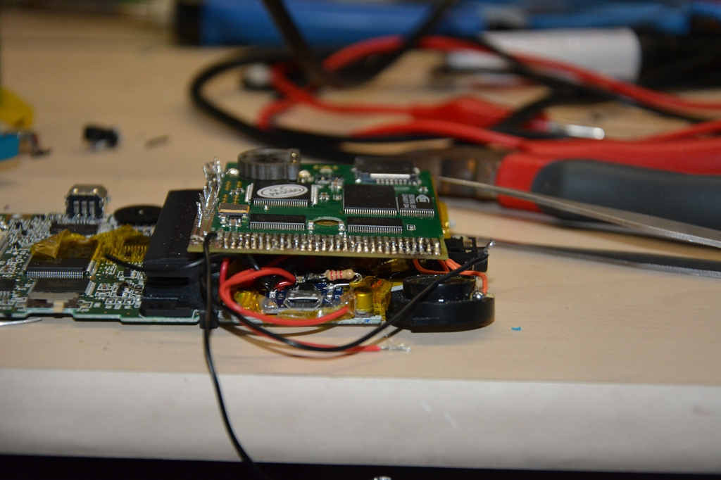
After that, soldering the stuff to the ribbon cable:
 |
| Nice view with ribbon cable. |
 |
| Third and last soldering process. :) |
Two LEDs were included into the case to indicate if the battery is charging or fully loaded:
 |
| Loading LEDs. |
After reassembling, the working test...it works:

Do you like the color? I do.
It is now possible to use the internal microSD-card OR an original cardridge. You can even take out the microSD-card without opening the whole case. It's not very beautiful but it makes its job.
 |
| microSD-card slot. |
 |
| Switch for cardridge-or-microSD-operation. |
 |
| microUSB-slot for charging battery. |
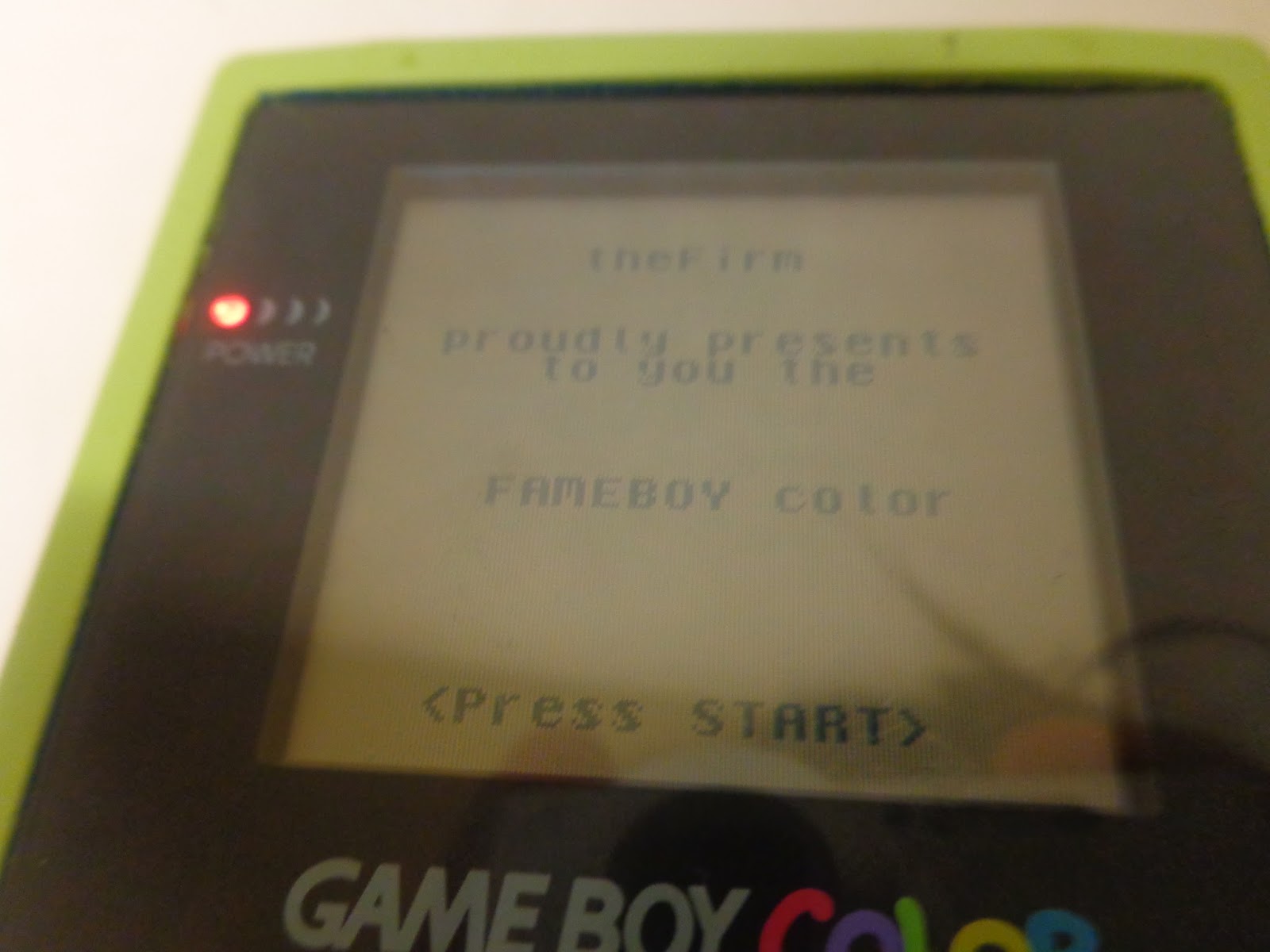 |
| Homebrew Software. YAY! |
That's it, all is working like it should. This project lasted over several months.
Sorry for the long post, I hope you enjoyed it.
Keine Kommentare:
Kommentar veröffentlichen