COOKIES

This site may be using cookies to melk you with your own data. I, ben0bi, am not the owner of this web service and I also do not maintain their servers. But the EU and the owner of this service think, that the user (me) has the responsibility to inform the consumer (you), that this website uses cookies. Again: I, ben0bi, NEVER use cookies. I am not responsible for the setup of this web service. I just present some information here and do not intend to spy on you for whatever reason ever. But (also again), I do not host this website nor do I maintain any servers related to this website nor do I benefit from using the cookies maintained from this service. I hereby give the responsibility for using cookies on blogspot back to the owners of blogspot.
Posts mit dem Label gameboy werden angezeigt. Alle Posts anzeigen

Donnerstag, 20. Dezember 2018

Mein eigener Gameboy

Also ich halte mich dabei an den Gameboy Zero, ausser folgendem:

+ Ich werde wohl die Hülle selbst drucken/bauen.
+ Der Gameboy soll auch Musik spielen und verschiedene Hacking-Tools haben. :)

Das ist ein "Work-in-Progress" Artikel, also...

ACHTUNG: JEGLICHE Elektronik, welche ich bestellt und in Lego eingebaut habe, ist kaputt gegangen. (Die selbstgebaute Platine nicht.) Was soll mir das sagen? Scheiss auf Scheiss-Plastik, denk ich mal. Ich bau sonst alles in Holz ein, da ist mir noch nie was kaputt gegangen.....Also: Rechne mit heftigen Verlusten, wenn du Lego verwendest. :)

Dies ist die aktuellste Version mit 2" Screen. Hier fehlt nur noch eine Halterung für Raspi und Akku sowie die Kabel zu den Buttons. (Das Screenkabel ist gebrochen, darum gibts dann noch eine ganz neue Version später mit 3.5"-Screen.)
2" Version mit Bauanleitung weiter unten.

Erstmal habe ich mir folgendes bestellt:

Einen Raspi Zero W
Bestell dir am besten gleich das Minimal-Kit, denn mir fehlt nun zum Beispiel der MikroUSB-zu-USB-Adapter. Den HDMI-Adapter hab ich vom vorigen Kit (ohne WLAN).

Hier mit angelöteten Pins, TV-Kabel und SD-Karte.

Einen 2" NTSC/PAL-Screen (den soll man angeblich ganz einfach anhängen können)
(Ich wollte eigentlich einen 2.5"er aber den gabs nicht. 3.5" sind dann schon zu gross für einen originalen Gameboy.) (Neu: Lieber zu gross als zu klein, also bestellt mal schön den 3.5er, der 2er ist nämlich unleserlich klein.)

Etwa so unleserlich ist es auch in echt. :)
Und eine MicroSD Karte brauchts natürlich auch noch. Da mach ich keine Werbung für, weil man nur noch minimum 16GB bekommt. Ich will aber weniger, um dann ein "kleines" Image zu ziehen...egal. :)

Abgewinkelte Pins und Doppelpins (siehe erstes Foto)

Strom hab ich noch zum Testen. Da kommt dann später natürlich ein Akku dran.

Desweiteren noch eine/zwei Platinen für die Buttons und so kleine Pushbuttons zum draufstecken.
Davon mindestens sechs: Dpad = 4 und A+B (noch OHNE Start und Select)

Software, Computer-Hardware

Dann hab ich mir die Recalbox für den Zero gezogen und mit Etcher auf die microSD gebrannt.

(Vorher hab ich raspbian drauf gemacht, aber recalbox geht gleich out-of-the-box)

Das Ganze am (normalen) Bildschirm angesteckt, läuft.
Recalbox installiert sich selbst beim ersten Mal.

Den Bildschirm habe ich mit einem zweiten USB-Netzteil angeschlossen...leuchtet = läuft. :)

Lustigerweise hat die ADAFRUIT-Box, mit welcher der Bildschirm geliefert wurde, genau etwa die Masse, die mein Gameboy haben sollte. Ich werde also diese vorerst mal nehmen, bis ich sie dreiDdrucken kann. (Neu: Lego, siehe unten)


Das Controllerboard vom Bildschirm habe ich mit Klettverschluss(-Klebeband) an die hintere Seite vom Bildschirm angemacht. Es muss sowieso unter dem Screen sein, um Platz für die (Gameboy-)Buttons zu haben. (Nein, die Buttons sind nun seitlich angebracht. Trotzdem ist es so viel weniger fitzelig zum Basteln. :) )

(Tipp: Anstatt dran rumzureissen, um den Klettverschluss zu trennen, kann man vorsichtig mit einem Messer mitten durch "schneiden".)

Den Bildschirm einrichten:

Der Bildschirm braucht seinen eigenen Strom!

Mit dem Kabel auf dem ersten Foto verbinden. Die TV-Pins sind angeschrieben auf dem Zero.

Mit F4 und dann Alt+F2 in den Terminalscreen.
Login: root, recalrootbox
https://github.com/recalbox/recalbox-os/wiki/Connect-your-recalbox-to-a-CRT-with-composite-%28EN%29

mount -o remount,rw /boot

nano /boot/config.txt

hier eintragen:

sdtv_mode = 0 bis 3, siehe Link
hdmi_ignore_hotplug=1

Ctrl-O, Ctrl-X

nano recalbox.conf

Suche mit Ctrl-W: global.videomode

global.videomode=default

Ctrl-O, Ctrl-X

Die Hülle, die Buttons

Erst wollte ich eine "normale" Hülle aus Plastik, Metall oder Karton bauen. Doch dann hab ich mir gedacht, warum nicht aus LEGO?

Also habe ich mir zuerst eine Hülle für den Screen gebastelt. Dieser selbst ist viel zu klein, aber es geht jedenfalls schon mal. Und darunter konnte ich noch eine Aussparung für Akku und weiteres einbauen.

Die Teile stammen hauptsächlich von diesen zwei Lego-Sets:
LEGO 42064: Ocean Explorer
LEGO 42065: RC-Racer

Ich möchte das modular bauen, darum hab ich mich dann an die Buttons gemacht: Man kann einfach ein paar lange Technic-Stäbe aneinanderlegen und dann mit Kreuzstäben die Buttons so anordnen, wie man will. Da mein Screenhüllendesign eher an den Gameboy Advance erinnert, baute ich mir zwei kleinere Pads nach diesem Schema für an die Seite ran.

Verworfene erste Version. Pad 1 links wurde hier (dafür) gelötet...*

Dann habe ich bei einer Platine, welche ich glaubs damals auf Conrad bestellt habe, die Buttons, welche ich glaubs auch damals dort bestellt hatte, angeordnet. Die Platine habe ich halbiert, für jede Seite eine Hälfte.

Nach ein bisschen Gefitzel und Rumgebastel passen nicht nur die Buttons, sondern auch die Platinen "perfekt" in die Hülle und werden von unten angeklemmt. Ein bisschen anpassen und die Buttons funktionieren besser als gedacht.

Nun gucken, wo man auf der Platine am besten die Leitungen hinlegen könnte, um die Buttons dann mit Steckverbindern an den Raspi zu machen....ich benutze hier gekrümmte Stecker.

Der Raspi hat eigene Pull-up/Pull-down Widerstände, die brauchts also nicht.
Hierbei konnte ich drei Buttons seriell in einer Reihe an GND anschliessen und musste nur den letzten noch separat mit GND verbinden. GND bzw. 5v ist der Pin ganz links, die anderen gehen an die GPIO-Eingänge.

Schliesslich hat mir die Grösse von der Bildschirmhülle nicht gefallen, deshalb habe ich das Bildschirm-Modul noch mal neu gebaut. Darum sieht man auf den Fotos auch etwas anderes als in der Bauanleitung.

Vorläufig endgültige Version für 2" Screens.
*..und die Padhülle musste an Pad 1 passen.

(Nur) Das Bildschirmmodul von unten gesehen.

Das neue Modul hält den Bildschirm auch gleich an der Stelle, das ging beim alten noch nicht. Da hat er nur pro forma reingepasst.

Hierbei darauf achten, dass der Bildschirm selbst über den Kreuzstäben, das Controllerboard jedoch unter den Kreuzstäben ist.

ACHTUNG: Der Aufbau geht, aber das Bildschirmkabel ist gebrochen.

FALSCH: Kabel über dem Kreuzstab

Mach ja nicht den Fehler, das Bildschirmkabel über den "einen" Kreuzstab zu legen "zur Stabilisierung". Alles schön lose machen und dann einfach überdecken.


RICHTIG: Bildschirmkabel unter/hinter dem Kreuzstab.
Hier sichtbar die untere Seite, einfach wie oben überdecken.


...darum musst du dir unten selbst einen Batterie- /Raspi-Kasten ausdenken.
Ich bestelle mir gleich einen 3.5" Bildschirm...

Die Pads mussten natürlich auch angepasst werden. Da ich für das eine Pad schon eine Platine gebaut hatte (siehe oben), wollte ich sie von der Form her beibehalten.

Die Anleitung gibts hier:
[TODO: Link zu Anleitung Pads und Centerteil]

Du kannst die Anleitung oben benutzen, wenn du den Adafruit 910 2" Screen bestellst.

Sie ist aber ziemlich verworren. Das hat der LDD (Lego Digital Designer) so gemacht, nicht ich...Darum bei den Pads: Erst die roten an die weissen Teile, dann die grünen und dann die Buttons so anordnen wie du willst. ;)

Die Pads sind jeweils seitenverkehrt genau gleich aufgebaut. Obwohl es unstabil aussieht, sitzen die Dinger "bombenfest".

Ich bin selber überrascht von der kuuuhlen Bauweise. :)

Uuuund das Kabel vom Bildschirm ist gebrochen....DA MUSS MAN EXTREMST AUFPASSEN.

Uund der Raspi ist auch am Arrrrrsch. Hier wird ganz sicher nicht "politisch korrekt" nur "A..." geschrieben, da könnt ihr aber Gift drauf nehmen.

Darum ist dieses Projekt vorerst mal eingestellt, vielleicht lade ich dann noch mal die Bauanleitung hoch. Ich hab ehrlich gesagt grad keine Lust mehr.

Weiteres folgt...

Sonntag, 21. Mai 2017

DIY: Emulator Teil 2: Setup Basisgerüst (JavaScript)

Im vorigen Artikel (Part 1) haben wir uns damit befasst, was ein Emulator ist. Nun kommen wir zum Programmieren selbst.

Wir brauchen für unser Grundgerüst verschiedene JavaScript-Bibliotheken.

  • jQuery -> Vereinfacht viele Dinge.
  • PixiJS -> Die Grafikbibliothek.
  • RUNPIXI -> Diese Bibliothek habe ich geschrieben, um PixiJS ganz einfach zu initialisieren.

Ich werde diese Bibliotheken nicht herunterladen, sondern einen direkten Link dazu angeben. Somit hat man erstens immer die aktuelle Version und zweitens wird Zeit gespart, wenn andere (fremde) Webseiten denselben Link benutzen. Der Browser hat die Datei dann schon im Cache gespeichert.

Ordnerstruktur

Generieren wir erst mal die generelle Ordnerstruktur und die ersten Dateien:

  • ./  --> Das ist das root/Basis-Verzeichnis.
  • js/  --> enthält alle JavaScript-Dateien.
  • css/ --> enthält alle CSS-Dateien.

[weitere werden folgen]

Ich benutze immer diese Ordnerstruktur für meine Web-Projekte, du kannst natürlich auch eine andere Struktur anlegen.

Nun legen wir ein paar verschiedene Dateien an:

  • ./index.html
  • ./css/base.css

css/base.css

Die Datei css/base.css enthält die grundlegenden Layout-Einstellungen:

html, body
{
width: 100%;
max-width: 100%;
height: 100%;
min-height: 100%;
overflow-x: hidden;
overflow-y: hidden;
}

div, html, body
{
padding: 0;
margin: 0;
}

#wrapper
{
position: absolute;
top: 0px;
left: 0px;
width: 100%;
height: 100%;
}

#pixiscreen
{
position: relative;
margin: 0 auto;
max-height: 100%;
min-height: 100%;
}

Der BODY und HTML Bereich wird auf die Fenstergrösse angepasst. Mit overflow-x: hidden wird alles versteckt, was breiter als das Fenster ist. Dasselbe wird mit der Höhe gemacht. Irgendwie ist das Div beim Chrome immer 0.2 Pixel grösser als das Fenster oder so, was zur Folge hatte, dass Scrollbalken auftauchten, welche dann sowieso noch ein bisschen mehr vom Fenster verdeckt haben. Overflow bräuchte es nicht, wenn das div zum Beispiel 99% Grösse hätte, doch ich will einen randlosen Bildschirm.

Das Padding- und Margin-Attribut wird auf 0 gesetzt, damit kein Rand übrig bleibt. Der #wrapper muss eine absolute Position haben, damit der #pixiscreen mit Margin horizontal zentriert werden kann. Dies hier nur zur Sicherheit, da der Pixi-Screen sowieso das ganze Fenster ausfüllt.

index.html

In die index.html kommt erstmal das HTML-Grundgerüst:

<!DOCTYPE html>
<html>
<head>
<meta charset="UTF-8" />
<title>EmulatroniX</title>
<link rel="stylesheet" type="text/css" href="css/base.css">
</head>
<body>
<div id="wrapper">
<div id="pixiscreen"></div>
</div>

<script src="https://code.jquery.com/jquery-3.2.1.min.js" integrity="sha256-hwg4gsxgFZhOsEEamdOYGBf13FyQuiTwlAQgxVSNgt4=" crossorigin="anonymous"></script>
<script src="https://pixijs.download/v4.5.2/pixi.min.js"></script>
<script src="http://cdn.rawgit.com/ben0bi/RUNPIXI.js/v0.6.4/RUNPIXI/RUNPIXI.js"></script>

<script>
function mainLoop() {}

$(document).ready(function()
{
RUNPIXI.initialize('pixiscreen', mainLoop);
console.log("Ready.");
});
</script>
</body>
</html>


Mit dem DOCTYPE-Tag wird dem Browser mitgeteilt, dass wir HTML 5 benutzen.
Das Meta-Tag stellt das Characterset auf UTF-8. Somit ist immer klar das gleiche Characterset definiert. Die CSS-Dateien werden im Header eingebunden, da sie vom Browser gebraucht werden, um das Layout aufzubauen. Die JavaScript-Dateien werden jedoch am Ende des Bodys hereingeladen, so dass das Layout im Aufbau nicht blockiert wird.

Das #pixiscreen-div ist im #wrapper-div, damit man es horizontal zentrieren kann.

jQuery ist eine Bibliothek, um viele Sachen in JS zu vereinfachen.
Den jQuery-Link bekommt man hier in dieser Form.

PixiJS ist eine JavaScript 2D-Graphikbibliothek, welche auf Geschwindigkeit ausgelegt ist.
Sie benutzt wenn möglich WebGL, ansonsten wird die DOM-Struktur benutzt.
Hierin werden wir die Textur erstellen, auf welcher dann der Bildschirm des Emulators gerendert wird (sogenannte RTT-Technik: Render-To-Texture - wobei hier nicht wirklich eine Szene auf die Textur gerendert wird, sondern nur die Pixel der Textur "direkt" ausgetauscht/verändert werden).
Den Link zu Pixi habe ich selbst aus den Releases von PixiJS herausgesucht.

Schliesslich ist RUNPIXI.js eine kleine Bibliothek, welche ich geschrieben habe, um den Initialisierungsprozess von PixiJS zu vereinfachen. Man braucht nun nur noch ein Kommando auszuführen, nämlich RUNPIXI.initialize(DOMContainerID, loopFunction), alles Andere macht RUNPIXI.

Wenn die Fenstergrösse geändert wird, merkt RUNPIXI das und passt automatisch den Pixi-Renderer an.

Schliesslich wird der Pixi-Bildschirm in dem kleinen Script am Ende initialisiert. Dazu muss es eine mainLoop-Funktion haben, welche nach jedem Frame aufgerufen wird. Diese benutzen wir gerade noch nicht. Man beachte, dass beim Namen des pixiscreens in der Initialisierungsfunktion kein # davor steht: RUNPIXI verzichtet auf jQuery.

Du kannst dem Pixiscreen deine eigene Hingergrundfarbe geben oder ihn sogar transparent machen, indem du die Farbe in der Initialisierungsfunktion als Parameter angibst. Die Farbe kann hexadezimal so angegeben werden: 0xRRGGBB wobei R für Rot, G für Grün und B für Blau steht.

RUNPIXI.initialize('pixiscreen', mainLoop, 0x111133); <-- Schönes dunkles Blau.
RUNPIXI.initialize('pixiscreen', mainLoop, 'transparent'); <-- Transparent. Man sieht nur, was du auch zeichnest.

Fertig!

Wenn du nun die Index.hmtl-Datei im Browser öffnest, sollte dein gesamter Browserbildschirm türkisblau sein (ausser du hast eine andere Farbe angegeben). Damit haben wir die Basis-(Graphik-)Engine initialisiert - das war ja noch ganz einfach. :)

Ich werde für jeden Part/Artikel auf GitHub ein Release vom jeweils aktuellen Master machen.

Das ist das Release für diesen Artikel:
https://github.com/ben0bi/EmulatroniX/releases/tag/Blog_Series_Part_2

Weiter gehts mit [Bitte warten, komplett neuer Aufbau] DIY: Emulator Teil 2.1: Der Emulator Bildschirm.


Samstag, 20. Mai 2017

DIY: Emulator Teil 1: Research

Dies ist eine deutsche Neuauflage meiner How-To-Make-An-Emulator-Serie, Teil 1.
Im originalen (englischen) Artikel ist ein ziemliches Chaos, da ich mich nicht wirklich für eine Entwicklungsumgebung entscheiden konnte. Nun habe ich JavaScript gewählt und werde auch dabei bleiben.

In diesem Artikel betreiben wir erstmal ein bisschen Forschung.

[EDIT]: Ich bin ein autodidaktischer Programmierer und habe Spass daran, Dinge selbst herauszufinden oder nachzuprogrammieren (Theorie zu Praxis, nicht einfach Code kopieren ;) ). Ich habe erst mal ein bisschen komplexere Artikel geschrieben um die Grafik aufzubauen. Das wurden dann schon ein paar Artikel, und bei diesen habe ich alles "selbst erfunden". Beim Emulator-Code selbst werde ich höchstwahrscheinlich einfach die zuunterst verlinkten Artikel ins Deutsche übersetzen.

Da schon nur der Grafikaufbau in mehrere Artikel ausgeartet ist, werde ich versuchen, eine etwas andere Nummerierung zu bewerkstelligen:

[EDIT] Ich habe nun das ganze Chaos aus den veröffentlichten Artikeln heraus genommen.
Grund: Es war in jeder Version zu langsam auf Standard-Laptops. Ich versuche dies nun mit Shadern zu bewerkstelligen. Bitte warten...

Mit Nummern versehen sind die Artikel, welche sich mit dem Aufbau des Grundgerüstes befassen, welches "extern" benötigt wird um den Emulator ("intern") anzuzeigen und zu bedienen. Die Grafik und das Basisgerüst werden in Teil 2 und allen zugehörigen Artikeln abgehandelt, also Teil 2.1_12.1_22.1_3, sowie Anpassungen 1 und Demo 1.

Mit Buchstaben versehen sind die Artikel, welche sich mit dem jeweiligen Emulator selbst befassen,
zum Beispiel [TODO] Gameboy A: Die CPU, Gameboy B: ...

Du findest alle Artikel zu dieser Serie auf dieser Seite.

Was ist ein Emulator?

Ein Emulator ist eine Software, welche eine bestimmte Hardware A auf einer anderen Hardware B simuliert, so dass man die Software, welche für Hardware A konzipiert wurde, auch auf System/Hardware B laufen lassen kann.

Die geläufigsten Emulatoren sind Konsolen-Emulatoren, welche zum Beispiel den Super-Nintendo auf einem PC emulieren. Es gibt aber auch für jegliche andere Hardware Emulatoren. Von einfachsten Chips bis zu den grössten Superrechnern kann man alles emulieren - wenn man genug (Rechen-)Zeit hat.


Ich habe einst einen Sega Master System Emulator, den ein Freund geschrieben hat, mit einer besseren graphischen Ausgabe beschert. Seine Software hat das Bild direkt in einem ganz kleinen Fensterchen auf dem Bildschirm ausgegeben. Ich habe dann eine 3D-Bibliothek mit einem Texturrenderer benutzt, um zu skalieren und verschiedene Filter darüber zu legen.
Leider habe ich den Sourcecode verloren.

Hier ist der Emulator für deine Befreudigung:
SMSEmu (homeserver) (direkter Download)
SMSEmu (OneDrive)

Dieser englische Artikel bietet gute Grundlagen.
http://fms.komkon.org/EMUL8/HOWTO.html

Zuerst möchte ich das Sega Master System emulieren, doch zuallererst muss eine Basis-Engine geschrieben werden mit der Grafikausgabe und weiterem. Die Grafik wird in Part 2 herbeiprogrammiert.

Diese ROMs (Spielkassetten-Dateien) sind für das Sega Master System. Sie dürfen jedoch nicht mit deinem Produkt ausgeliefert werden. Das wäre illegal. Ich biete sie hier nur an, damit man etwas zum testen des Codes hat.
SMSRoms.zip (homeserver) (direkter Download)
SMSRoms.zip (OneDrive)

Theoretische Überlegungen

Mein Ziel ist immer noch ein Multi-Purpose-(Konsolen-)Emulator, welcher aufgrund des geladenen ROMs entscheidet, welche Hardware dafür vorgesehen ist, und diese dann emuliert. Du könntest dann ROMs von jeder unterstützten Plattform in den selben Ordner kopieren und einfach das Spiel spielen, ohne dich um die Plattform-Auswahl kümmern zu müssen.

Der Emulator liefert ein Array mit Pixeldaten, die dann dargestellt werden können wie wir uns es wünschen. Somit ist es eigentlich egal, welche Engine man benutzt. Hauptsache man kann damit irgendwie Pixel rendern. Nachdem ich nun einige Zeit PixiJS benutzt habe, will ich es mal damit versuchen. Damit kann man wirklich schöne Sachen machen.

Fakten sammeln

Um einen Emulator zu bauen, muss man natürlich die zu emulierende Hardware kennen. Dazu gibt es meistens Dokumente, die aufzeigen, wie sie funktioniert. Dann muss man diese Hardware in Software nachbauen.

Ich möchte das Sega Master System (SMS) zuerst machen. Der oben genannte Freund gab mir dazu diesen Link, wovon er das oberste Dokument empfahl, welches er selbst gebraucht hat.


Dieses Dokument hier gibt mehr Informationen als alle anderen:

Der Gameboy wäre jedoch hier besser geeignet, da jemand schon einen JS GameBoy-Emulator geschrieben hat: 

Ich werde mich vorerst nach diesem Tutorial richten.

Doch darum kümmern wir uns, wenn die Grund-Engine steht.

Anders als im oben verlinkten Artikel, werden wir zuerst die Grund-Engine bereit stellen, in der dann alle Emulatoren ausgeführt werden können. Dies wird dort "erst" ab Kapitel 5 [gar nicht(?)] abgehandelt und ich möchte dir nicht die Entscheidung der Wahl deiner zu emulierenden Hardware abnehmen, nur weil das Grundgerüst erst "später" gemacht wird.

Im Grundgerüst wird der Bildschirm aufgebaut und gezeichnet, sowie der Sound ausgegeben.

[edit 2019] Ehm sorry aber ehm.. ich nehm trotzdem Unity und C# weil man jetzt endlich (gratis) auf der Textur herum zeichnen kann, also...

Oder direkt mit: [TODO] Gameboy A: Die CPU

Mittwoch, 4. November 2015

GAMEBOY Devkit ben0bi Edition

I downloaded the Gameboy devkit and played around with it like here.
In the developing process, there were some stuff downloaded which I included in the original devkit.

Here are the downloads:
gbdk_ben0biEdition.zip from Mirror 1 (Onedrive)
gbdk_ben0biEdition.zip from Mirror 2 (Homeserver)

And here is what you get for it (copied from README.txt):

First of all, you need to call do.path in every new terminal window, else the paths are not defined. Call it like that: . do.path in your gbdk-root directory. (NOT ./do.path)

Please look also at this post, my friend SneezyCerritus got all out of an old Gameboy Color.


Additions:
+ gbdk-doc downloaded from sourceforge.net (If you can redeem 8.8Mb for the Nintendo Manual,  you can do that with this 50kb for sure.)

+ A shell script to set the path for GBDKDIR. Please change this to your own path.
    + do.path ->    Call it with: ". do.path" because "./do.path" will not
            set the variable globally.

+ RGBDS (compiled and source) for fixing the code to run on real GameBoy hardware.

+ Some PDF-resource.
    + GBCPUman.pdf             -> GameBoy CPU Manual by some people from the internet.
                        This one contains some tips and tricks.
    + gb_programming_manual.pdf    -> Original document by Nintendo.
                        I have no idea where I found this.
                        Biggest file of the whole compilation. ;)

+ A tile editor for LibreOffice: assets/ben0bis_GB_TileEditor.
    + And a font created with it, spread over several files in the assets/new folder.
    + Also as zip-file if you do something wrong.

+ New code from myself in the ben0bi-folder with some shell-scripts to automate.
    + ben0bi/credits    -> Credits of this whole project.     (Not finished yet)
    + ben0bi/IRremote    -> An IR remote for your TV.         (Not finished yet)

+ Some shell scripts from myself and updated Makefiles to use with libraries. (multiple .o-files)
    Look in the subfolders of the ben0bi-folder:
    + Makefile    -> the original one from the examples does not work properly.
    + do.all    -> calls all the other do-files and starts the game after compiling.
                It uses VisualBoy Advance (vba) as emulator, please install it.
    + do.compile     -> calls "make clean" and then "make"
    + do.fix    -> fixes the file to use on real GameBoy-Hardware.

        You need to set the proper filename/s in all of this files.


+ New Examples, stolen from the internet:
    + examples/burlyGBC_src    ->    a little game where you are a bear.
                I learned how to use graphics with that one.
                Contains the original tile editor tiles17.xlsx
    + examples/IR        ->    contains some source to use the IR sensor.
                (code not used yet.)

Samstag, 29. August 2015

GameBoy Color: Hardware Modding

Like mentioned in this post here, my friend SneezyCerritus gets the best out of an old GameBoy Color on the hardware side. I wanted to load my homebrew GBC-modules so he ordered a cardridge with a microSD-slot. Then he had the idea to put that cardridge inside the GBC so we could either use games from the microSD slot (all there are ;) ) or use an original Gameboy-cardridge on the other side, without taking the microSD-cardridge out.

Also, he decided to put an accumulator pack and a microUSB-accumulator-load-slot into it.

WARNING: This project is freaking expensive and only for enthusiasts. It is a nice thing but it's very costly. I bet you can never sell it for the price below, which is:
--> more than 300 CHF and counting...

This is the device we are talking about, in exactly that color (but this images are stolen from the internet because we started making pictures after the start of modding.)


And here is an image of the back, for your consideration:


Here is what we got to build into the case:
http://opcoa.st/JGdT7

It's an "Everdrive GB V1.2"

Also he got a Li-Ion-Accumulator-pack, a loading-chipset hardware breakout and a miniUSB-plug.

Accumulator, USB-and-loader-breakout and Everdrive.

First a view from the workplace: In front you see a not-yet-functional 3D-printer (software issues). The GameBoy workplace is just beneath it, you cannot see it.
Workplace
Here you see all the parts, on the backside is a cutout because there were not enough space.
All the needed parts.

Ok, first he opened that the GBC and the Everdrive. For the GameBoy you need a special screwdriver with three 3 "corners". (NOT a triangle! It's like a normal screwdriver but...triple.)

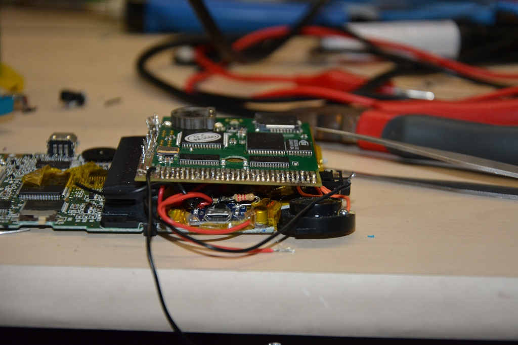
He soldered a cable to each pin of the GameBoy-hardware and put in the Accumulator and loading-stuff.
First try with cables.

Soldering the cables together.

After that he soldered it to the Everdrive and tried to close the case.
All done, does it fit?

It's not possible, so he unsoldered the Everdrive and made a special PCB only to connect the two pieces together.
PCB for the second try.
That glassy thing is a selfmade PCB-creator. It's just some ultraviolett LEDs and a glass plate and some covering, I don't know how it works exactly.

He then cut the wires short and soldered the PCB on the GBC and the Everdrive on the PCB.
 
PCB, GBC and Everdrive soldered together.

PCB sideview.

Problem is, it will not fit to the case either. The case needs to be extended, with some parts changed.

SneezyCerritus used some 2-component superglue to create the outer shell of the expansion on the original case. Then another friend removed the inner parts, until only the superglue-case was left.
Some glue on the right place...

..makes the shell bigger.

Getting rid of the stuff inside.
When you fail in this (there was a hole where no hole should be), you can use some more glue to fix it, easy. The battery case cannot be opened anymore so the accumulator is necessary from now on.

He put it all together but it won't fit either. The PCB was to big.

The last solution for that issue (which finally worked) was to take a ribbon cable like on that image here:
 

Here you see an image from the de-soldering process, with the ribbon cable in the background.
De-soldering the PCB.

After that, soldering the stuff to the ribbon cable:
Nice view with ribbon cable.

Third and last soldering process. :)

Two LEDs were included into the case to indicate if the battery is charging or fully loaded:
Loading LEDs.

After reassembling, the working test...it works:


Do you like the color? I do.

It is now possible to use the internal microSD-card OR an original cardridge. You can even take out the microSD-card without opening the whole case. It's not very beautiful but it makes its job.

microSD-card slot.
Switch for cardridge-or-microSD-operation.
microUSB-slot for charging battery.
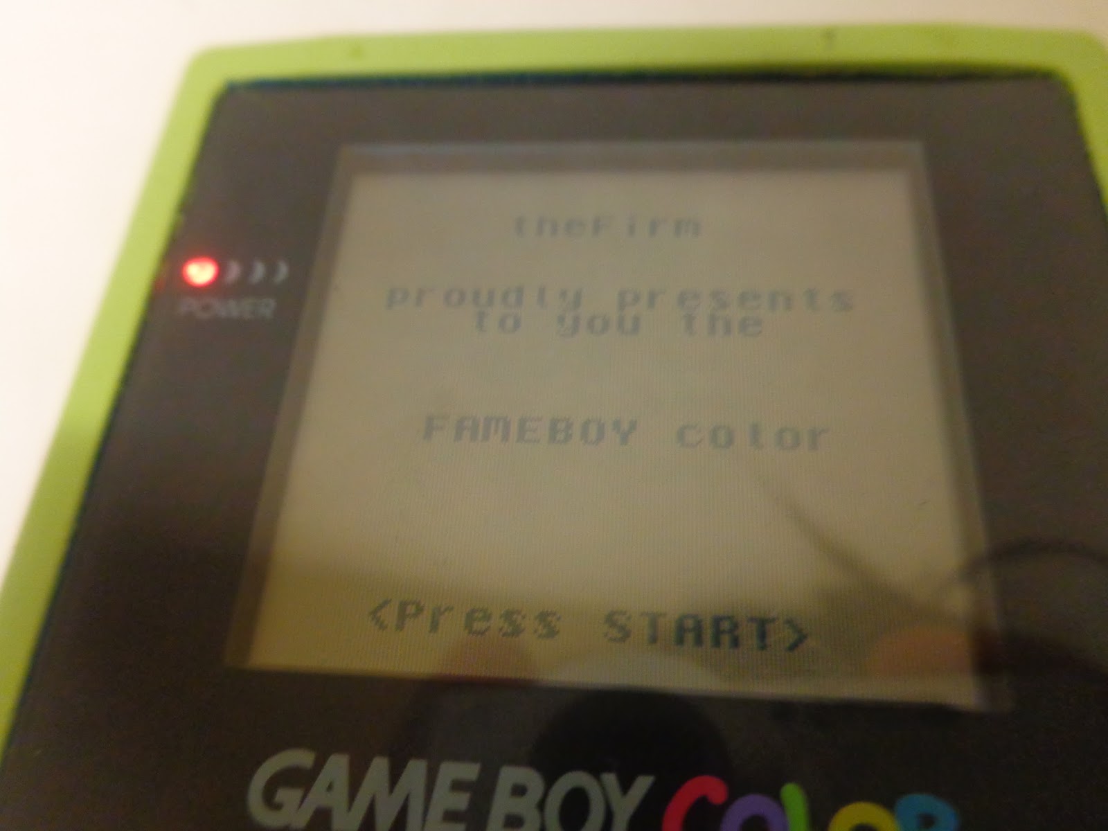
And finally, homebrew software running on the "original" device:
Homebrew Software. YAY!

That's it, all is working like it should. This project lasted over several months.

Sorry for the long post, I hope you enjoyed it.

Sonntag, 9. August 2015

GameBoy Color: Getting Started

I found a Gameboy Color somewhere, and while my friend is modding it to the max on hardware side, I am unable to find any programming sources explicitly for GBC.

All I can find is for GameBoy (original) or for GameBoy Advance.

I want to program the infrared sensor which is GBC only, so I need some reference for GBC.

First of all, when using GBC mode, you need to modify some stuff to "get the graphics back" (which you already have in your GameBoy-NonColor-Game).

It lasted some time to just get the printf()-output back to screen, and here is what you have to do.

Development Setup

[EDIT] You just need to set up palettes and use the GBCSetup-method below. The rest is just for consideration, you can also use gb/drawing.h to draw stuff and print text.

Linux:
Search for a good GameBoy emulator. I am using VisualBoy Advance, which is available over the Marketplace from Ubuntu.

Download the GameBoy Development Kit GBDK from sourceforge.net:
http://sourceforge.net/projects/gbdk/ 
gbdk ben0bi Edition ;)

1. Unpack the archive somewhere. Mine is in the users root directory.
2. Set the path to your installation. Type in your console:
export GBDKDIR=/home/ben0bi/gbdk

Now you should be able to compile the examples. Go into the examples directory and type make.

If all went good, you should have several .gb files now which you can start with the emulator.

In the directory examples/colorbars you will find a Makefile which sets the flag to GBC instead of GB in the last two lines.

Copy it to your project folder, alter the file names in it and set the right path to lcc on the top. You can use it yourself now.

Here is a Makefile which compiles two source files into a GBC-rom.
I needed some time to find out how the second file (core.c) has to be added to the compile-workflow as a "library".

It patches byte 0x143 in the header of the ROM to the value 0x80 (GB + GBC Mode) or 0xC0 (GBC only mode)
-> -Wa means "pass the next arg directly to the asm-compiler."
-> -Wl means "pass the next arg directly to the linker".
-> -ypX=Y means "patch byte X to value Y"

The Makefile

I don't get exactly how it works, but it..works..like that.

WARNING: The first two commands were suited otherwise. I got the parameters wrong by some functions, so I changed it.
They were made for a project with just one source file.
(Or I don't get it at all)

Instead of:
    $(CC) $(CFLAGS) -c -o $@ $<
I wrote:
    $(CC) $(CFLAGS) -c $<

-c means "compile only" and -o means "create output file" or something like that.
Some stuff only needs to be compiled and then linked together.

# Set the path to the compiler with some parameters.
CC    = ../bin/lcc -Wa-l -Wl-m

# Some other params... (why here?)
CFLAGS    = -DGBDK_2_COMPAT

# To get your other .c files compiled, add them here as .o-file
BINS    = mylib.o \
                someCfile.o \
                IRremote.gbc

# Refer to BINS for "make all" / "make"
all:    $(BINS)

# What files are created from which files...(I think. (?))
%.o:    %.c
    $(CC) $(CFLAGS) -c $<

%.o:    %.s
    $(CC) $(CFLAGS) -c $<

%.s:    %.c
    $(CC) $(CFLAGS) -S -o $@ $<

%.gbc:    %.o
    $(CC) $(CFLAGS) -o $@ $<

# The clean command: Just remove all the stuff which is not needed.
clean:
    rm -f *.o *.lst *.map *.gb *.gbc *~

# Link file, and write 0x80 at position 0x143 in header
# 0x80 is GBC compatible, 0xC0 is GBC-only.
# link together all the files which are created -> add your .o files.
IRremote.gbc:    IRremote.o
    $(CC) $(CFLAGS) -Wl-yp0x143=0xC0 -o IRremote.gbc IRremote.o mylib.o someCfile.o

Ok, we can now generate GBC-only-ROMs, but they show nothing with normal GB-code.

The Code

First, a hello world program which runs on normal GameBoys, no problem at all:

#include <stdio.h>
#include <gb/gb.h>

int main()
{
    printf("Hello World!");
    return 0;
}
You don't even need to give some compiler options, just type lcc -o myfile.gb myfile.c (You need to give the right path for lcc, though) and test it with vba myfile.gb.

Now, if you patch it, it won't work properly anymore.

Patching goes like this (without Makefile):
lcc -c -o myfile.o myfile.c
lcc -o -Wl-yp0x143=0x80 myfile.gb myfile.o
Remember: GBC ONLY needs the flag 0xC0 instead of 0x80.

Well then, let's do some stuff to get that "Hello World!" back on screen.

The following shows how to set up tiles (for background, I think foreground is almost the same.) and colour palettes to use with GBC. Finally some stuff will be drawn on the screen. Problem here is that printf and tiles don't work well together. (It works for printf if you only do the palette stuff.)
We need one or more palettes with some colours in it. We can have up to 8 palettes, but one is enough for now. Also, we need to check the hardware if it is really a GameBoy Color (only this one has IR-stuff.) These are the Values to check, they are defined in gb/gb.h ;)
DMG_TYPE 0x01 /* Original GB or Super GB */
MGB_TYPE 0xFF /* Pocket GB or Super GB 2 */
CGB_TYPE 0x11 /* Color GB */

Here is the source code for the absolute minimum. You can extend it at your belief, there are some comments about "the other stuff".

#include <gb/gb.h>
#include <stdio.h>

//+++++++++++++++ Stuff to check for Hardware-Version.
extern UBYTE _cpu;          /* Check this var for... */
// the other defines are in gb/gb.h //+++++++++++++++ EndOf Stuff for Hardware-Check

//+++++++++++++++ Palette Stuff
// Some palette indexes. Possible: 0 - 7
#define PAL_BACK_DEFAULT  0  // Background default palette on index 0
#define PAL_DEFAULT 0 // That would be the palette index for sprites. (Foreground)

//********* Palette Definitions -> Here are the colors.
// 4 Shades: First is Background Color (black), last one (blue) is Font Color
// Positions in the Tile-Editor (later): 0,2,1,3

const UWORD pal_def_default[] = { RGB_BLACK, RGB_WHITE, RGB_GREEN, RGB_BLUE };
// ... define some more ...

//********* EndOf Palette Definitions
//+++++++++++++++ EndOf Palette Stuff

//+++++++++++++++ Some Tile Data
// I will only show how 8x8 tiles work,  I don't know if 8x16 is just 2px
// instead of one or if it can be defined separately.
// One tile has 16bytes assigned, that are 2bit for each pixel = 4 colours.

// the hardware start adress -> must be a define to make an enum later.
#define adress_characters 0x00     
const UBYTE count_characters=2;  // how many characters are there
const UBYTE data_characters[] =   // the characters (tiles) itself.
{
      0x00, 0x00, 0x00 0x18, 0x00, 0x24, 0x00, 0x42, 0x00, 0x42, 0x00, 0x7E, 0x00, 0x42, 0x00, 0x42, // A - starts at adress Adress+0
      0x00, 0x01, 0x02, 0x03, 0x04, 0x05, 0x06, 0x07, 0x08, 0x09, 0x0A, 0x0B, 0x0C, 0x0D, 0x0E, 0x0F  //  some junk ;) - starts at adress Adress+1
// ...don't forget the comma ^
}

// if you have many tiles in one array, you can refer to the tiles with an enum:
enum
{
     tile_A=adress_characters, // adress_characters CAN NOT be a variable. :(
     tile_B, tile_C,   // ... every name here is adress_characters + x ;)
} eTiles_characters;

// now every tile is at (tileadress)+position where position a counter for each whole tile of 16bytes. (a=0, b=1, c=2 etc.)

//+++++++++++++++ EndOf Tile Data

//+++++++++++++++ Function Bodies
void GBCSetup();       // this method sets up the graphics for GBC.
void load_palettes();  // load and assign palettes into hardware.
void load_tiles();        // load the tiles into the hardware.
//+++++++++++++++ EndOf Function Bodies

int main()
{
   GBCSetup();

   printf("Hello World!");
   return 0;
}


Now load the palettes and tiles into the hardware and then the almigthy GBCSetup function:
// load the palettes
void load_palettes()
{
// Params: Palette-Index, Unknown, Start-Position

    set_sprite_palette(PAL_DEFAULT, 1, &pal_def_default[0] );
    // ...define some more (foreground)...

    set_bkg_palette(PAL_BACK_DEFAULT, 1, &pal_def_default[0] );    // ...define some more (background)...
}

// load the tiles into the hardware.
void load_tiles()
{
    // load the background tiles.
    set_bkg_data(adress_characters,count_characters, data_characters); // start adress, tile count, tile-array   
}

// Set Up GameBoy Color
void GBCSetup()
{
    if(_cpu!=CGB_TYPE)
    {
        // It's not a GBC, nothing to do here.
        return;
    }

    // turn off display and disable interrupts.
    disable_interrupts();
    DISPLAY_OFF;

    // set tile size in LCDC-register. 0x67 = 8x16 tiles.
    LCDC_REG = 0x63; // 8x8 tiles

    // load palette data
    load_palettes();

    // Put the tiles into the tile-buffer.
    load_tiles();

    // reset display and re-enable interrupts.
    DISPLAY_ON;
    enable_interrupts();
}

Now we have a tile (exactly two but the last one is junk.)
We can put the tile on the screen with some functions...

A function to draw a background tile:
// the define is just a shorcut. #define render_back_tile(x,y,tile,palette) render_background_tile(x,y,tile,palette) void render_background_tile(UBYTE x,UBYTE y,UBYTE w, UBYTE h,UBYTE tileIndex,UBYTE paletteIndex)
{
    UBYTE c, d;
    UBYTE til[]={tileIndex}; // somehow it is needed as array. Idk why.
    UWORD pal[]={paletteIndex}; // somehow it is needed as array. Idk why.

    VBK_REG=0; // set background tileregister or something)
    set_bkg_tiles(x,y,w,h,til);  // put the tile into hardware (only with VBK_REG==0)

    // now set it to set the palettes.
    VBK_REG=1;

    // set the palette at that position, maybe for multiple tiles.
    if(w*h==1){
         set_bkg_tiles(x,y,w,h,pal);
    }else{
         // if we are rendering multiple tiles, we need to set the attributes for all tiles.
        for(c=0;c<w;c++)
            for(d=0;d<h;d++)
                 set_bkg_tiles(x+c,y+d,1,1,pal);
    }
}

For drawing something, you just have to wait until the vblank-interrupt is called with wait_vbl_done(); after or before drawing. (I don't see any difference on the emulator.)