COOKIES

This site may be using cookies to melk you with your own data. I, ben0bi, am not the owner of this web service and I also do not maintain their servers. But the EU and the owner of this service think, that the user (me) has the responsibility to inform the consumer (you), that this website uses cookies. Again: I, ben0bi, NEVER use cookies. I am not responsible for the setup of this web service. I just present some information here and do not intend to spy on you for whatever reason ever. But (also again), I do not host this website nor do I maintain any servers related to this website nor do I benefit from using the cookies maintained from this service. I hereby give the responsibility for using cookies on blogspot back to the owners of blogspot.

Samstag, 4. März 2017

Programmierung eines brandneuen ATmega328p mit Arduino UNO

Programmer auf Karton

Programmer auf PCB


Originaler Artikel (englisch)

Einführung

In diesem Artikel erkläre ich, wie ich meine brandneuen ATmega328p-Chips mit meinem Arduino UNO (Rev. 1 oder 2) programmiert habe. Die Informationen sind zwar im Web (englisch) verfügbar, doch es dauerte eine Weile, um Alles zusammmen zu bringen. Hier wird nun alles erklärt, vom Aufbau des Test-Boards bis zum hochladen eines Arduino-Programms auf den Chip.

Ich habe einen Arduino UNO, welcher mit einem ATmega328p-Chip bestückt ist. Ich dachte,  OK, dann bestellen wir mal ein paar von denen. Hier war einfach die Kostenfrage entscheidend: Ein Arduino kostet so um die 30 CHF, der Chip selbst aber "nur" um die 5 CHF.

Hier ist das Pin-Diagramm des ATmega328p nachdem der Arduino-Bootloader auf den Chip geladen wurde:
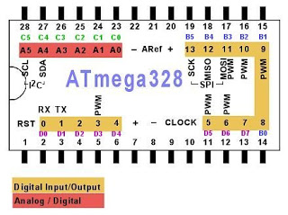

Man beachte hier die runde Kerbe links. Diese ist auf jedem Chip dieser Bauart, sowie auch auf den Halterungen dazu. Sie zeigt an, in welche Richtung der Chip eingelegt werden muss (Kerbe zu Kerbe).

Liste der benötigten Teile

Im Gegensatz zum Originalartikel werde ich hier einen Link zu jedem Bauteil angeben.
Diese Links werden meist auf ELV.de verweisen, um möglichst nur eine Bestellung machen zu müssen.

Du brauchst die folgenden Dinge:

+ Einen Computer. ;)
+ 1x Arduino UNO (oder Duemilanove oder so, probier es aus.)
+ 1x ATmega328 chip, DIP 28, brandneu, ohne bootloader oder so darauf.
+ Ein Experimentierboard (oder Karton oder PCB und ein Lötkolben ;) )
+ Verbinder-Kabel (Link als Beispiel)
+ 1x 10k Ohm Widerstand (Link als Beispiel)

Diese Dinge habe ich desweiteren gebraucht. Ich weiss nicht, wie man auf den internen Timer (8MHz) programmiert, denn ich wollte unbedingt die volle Leistung herausholen...weiss Gott, warum:

+ 1x 16Mhz Quarz Schwingkreis
+ 2x 22pF Kondensatoren (ACHTUNG: Der Quarz oben hat eine maximale Last von 18pF, der Wert hier ist aus dem Originalartikel und ich habe keine Ahnung, wie ich darauf gekommen bin.)
+ Optional noch 1x On/Off Schalter, um den externen Oszillator aus zu schalten.

Zuletzt die LEDs. Sie werden nicht unbedingt gebraucht, können aber bei der Entdeckung von Fehlern behilflich sein:

+ 1x Blaue LED, welche den Herzschlag des Host-Arduinos repräsentiert.
+ 1x Grüne LED, welche leuchtet, wenn die Software erfolgreich auf den Chip übertragen wurde.
+ 1x Rote LED, welche bei einem Fehler aufleuchtet.
+ 1x Gelbe LED, welche zum Testen des Chips (Blink-Sketch) benutzt wird.
+ 4x 100 Ohm Widerstände.
(Die Links dienen als Beispiel)

Alle Teile da? Dann fangen wir mal an...

Arduino IDE

Um den Arduino und den Chip zu programmieren, benutzen wir die Arduino IDE. Es muss mindestens Version 1.0.1 sein, oder auch tiefer als 1.0.0, doch mit Version 1.0.0 lief der serielle Port mit 9600baud, auch wenn man 19200baud angegeben hat. Die aktuelle Version ist 1.8.x, das sollte also kein Problem sein.

Du findest die neueste Version hier:

Neuerdings gibt es auch eine Online (Web-)Version der Software, doch ich weiss nicht ob und wie das funktioniert.

Den Arduino aufsetzen

Bitte entferne alle Verbindungen zu deinem Arduino um Software darauf hoch zu laden. Dies dient der Sicherheit der Chips (Sowohl des Hosts als auch des Clients.) Um das einfacher zu machen, laden wir die Software schon jetzt auf den Arduino. (Auf die Arduino-Platine, nicht auf den ATmega328-Chip, welchen wir programmieren wollen.) Wenn die Software erst mal installiert ist, brauchen wir daran nichts mehr zu ändern.

Wir brauchen diesen Sketch: ArduinoISP2c.zip (auf meinem Onedrive-Account aber nicht von mir.)

+ Öffne die IDE und verbinde den UNO mit dem Computer.
+ Lade den ArduinoISP2c-Sketch in die IDE.
+ Wähle den richtigen Port im Tools-Menü aus.
+ Drücke nun auf "Upload" und warte bis es fertig ist.

+ Um nun den Chip auf dem Experimentierboard zu programmieren, müssen wir einen anderen Programmer auswählen. Gehe nach Tools->Programmer und wähle "Arduino as ISP" aus. Prüfe das doppelt und dreifach nach, sonst überschreibst du deinen UNO!!

(Im Originalartikel steht: JETZT den Sketch hochladen, und danach den Arduino mit dem Experimentierboard verbinden - das ist unlogisch und ich erwähne es hier nur, falls etwas schief gehen sollte.)

+ Verbinde nun den Arduino mit dem Experimentierboard (Siehe unten)

Dies ist der Schaltplan für das Experimentierboard mit einem verbundenen Arduino:

Und so sieht es auf dem Board selbst aus:

Hier ist nun noch ein Schaltplan, um einen Programmer zu bauen, sowie ein Bild des Platinenentwurfes. Es ist genau das selbe wie oben, nur dass hier die Verbindungen zum Arduino durch eigene Pins ersetzt wurden. (Hier Female, man kann aber auch Males benutzen.)


Nachdem wir nun unser Board verbunden oder unseren Programmer gebaut und verbunden haben, können wir endlich mit dem lustigen Zeug beginnen.

Alle benötigten Dateien findest du auf dem GitHub-Repository zu diesem Artikel:
http://github.com/ben0bi/BATmegaProgrammer

Zuerst mal AVR, dude..

AVRDUDE ist ein Kommandozeilen-Tool, welches mit der Arduino IDE mitgeliefert wird. Da ich es nicht finden konnte, habe ich es separat noch einmal heruntergeladen. Mit diesem Tool werden wir die "Fuses" setzen, welche man mit "Jumpern" oder den ganz kleinen Schaltern vergleichen könnte, welche es früher auf Mainboards gegeben hat...nur, dass die Fuses in Software "verbaut" sind und nicht in der Hardware. ;)

Mit den Fuses stellen wir ein, dass der Chip mit dem externen Oszillator-Quarz laufen soll anstatt mit dem internen.

Wenn du andere Vorlieben hast, kannst du mit diesem Tool die Werte der Fuses kalkulieren:
http://www.engbedded.com/fusecalc

AVRdude ist wie schon beschrieben ein Kommandozeilen-Tool und muss mit einigen Parametern gestartet werden. Wir werden die folgenden Parameter benutzen:

-c: Wähle den Programmer aus. Wir werden hier avrisp benutzen.
-p: Der chip, welcher programmiert werden soll. Hier m328p.
-P: Der Geräte-Port des Arduinos. Es ist com3 auf meinem Windows-Computer.
-b: Die Baud-Rate, welche benutzt werden soll. Wir brauchen 19200 baud.
-U: Führe einen Befehl auf dem Chip (und nicht auf dem Arduino) aus.
-u: Muss mitgegeben werden, wenn man die Fuses setzt. Sagt einfach: JA, ich WILL WIRKLICH die Fuses setzen.

Ok. Erstmal prüfen wir, ob der Chip bereit ist:
avrdude -c avrisp -p m328p -P com3 -b 19200
So etwas wie "All OK sollte nun in der Konsole aufpoppen.

Wenn alles OK ist, werden wir nun die Fuses setzen. Ich weiss nicht genau, was all die Werte genau tun, ich weiss einfach, dass es funktioniert. Ich musste den Wert für die Low-Fuses selbst herausfinden, doch die anderen Werte bekam ich von einer anderen Website (siehe oben).

Erstens wird der Chip auf den externen 16MHz Oszillator vorbereitet, desweiteren wird auch das Lock-Byte auf 0x0F gesetzt (warum auch immer) und ein paar andere Sachen.
avrdude -b 19200 -c avrisp -p m328p -P com3 -U efuse:w:0x05:m -U hfuse:w:0xD2:m -U lfuse:w:0xFF:m -U lock:w:0x0F:m -u

Das ist alles. Um die Fuses zu prüfen, kann dieser Befehl benutzt werden:
avrdude -b 19200 -c avrisp -p m328p -P com3 -U hfuse:r:fusehigh.txt:s -U lfuse:r:fuselow.txt:s -F

Damit werden die Werte der gegebenen Fuses (hier: hfuse und lfuse) in die jeweilige Textdatei geschrieben (hier fuselow.txt und fusehigh.txt).

Den Bootloader brennen

Nun, da alle Fuses gesetzt sind, der Chip OK ist und den externen Quartz benutzt, und der Programmer der Arduino IDE auf "Arduino as ISP" gesetzt ist (!!!), können wir den Bootloader auf den Chip auf dem Experimentierboard brennen.

Wähle einfach Tools->Burn Bootloader in der IDE und warte ein bisschen. Wenn nichts schief gegangen ist, solltest du nun Arduino-Sketches auf den Chip laden können.


Der letzte Test

Lade nun den Blink-Sketch über File->Examples->01. Basics->Blink in der IDE und ändere den Output-Pin (13) auf 8.

Lade den Sketch auf den Chip über Sketch->Upload via Programmer in der IDE. Prüfe aber erst, ob der Programmer immer noch auf "Arduino as ISP" gestellt ist!

Die gelbe LED auf dem Experimentierboard sollte nun blinken.

Ich hoffe, das hilft.

Dienstag, 3. Januar 2017

microSD-Card Holder for Metal Swatch.

So, you have this cool Swatch-watch and don't know how to move that mechanical stuff to the next millenium? You ever wanted to be a spy or something? Then this is for you...


This is a spy-style microSD-card holder for the "Swatch Sistem Boreal YIS401G" and other watches with the same metal wrist, created on TinkerCAD.com and printed with a Dremel 3D-printer.
(Don't worry, the link for the TinkerCAD model is at the bottom of this post.)


First I wanted to make a round inner part which can be turned to open it. But this would not fit in.
So I made a "cheap and dirty" rectangular inner part which...is better than I thought.

The microSD-card locks the inner part from falling out. But it does fall out easily if it is "unlocked".


The outer part fits into the latch of the metal wrist, it can be "clicked in"...
After some trial-and-error 3D-prints I had the right end product, which properly "locks" and "unlocks" and fits into place at all. 


As you can see here, it does not fit exactly when you wear the watch. But there is no less comfort for me, and it is almost invisible. If I had used 3dMax or such, that would be no problem to fix. ;)

Back: Almost invisible
Front + Seen from the hand to the head.
 And here's some sWatch-Porn:


I hope you like it. Here is the TinkerCad-model.

Please like, comment and share. Thanks for your attention.

Mittwoch, 12. Oktober 2016

The Green Lantern: Computerized Glowing Bedside Table

This is a little project I made "out of nothing".

I had a standard wooden crate left, which I already used as bedside table.

Buy it here (Switzerland): Buy Wooden Crate

I have a cheap laptop (Packard Bell, 13 or 15 inches(?)) which fits EXACTLY into the crate. The crate is 37cm broad, that you know it.

Only the screen needs to be turned from the inside to the outside.

The keyboard and the touchpad are non functional anymore. I thought, ok, now I can turn the screen to the outside without a big loss. If it is gone, it's gone. But it works...

Here is how you get the screen off. Just turn it and fiddle it back on.
https://www.youtube.com/watch?v=IqNpRGFgg0Q

STOP at 3.50! Don't pull out the cable! Just turn it 180degrees viewed from the top, not from the side, else the screen is mounted upside down.


You then need to adjust the cover a little bit with the dremel, so that you can use the back side on the inside and the front side on the outside. I removed the camera, I don't need it. The cover will not fit exactly (on the side), but it will cover as mostly as good as in the original configuration. You can even put the screws for the cover back on (with this model, at least).


Then I got some nails and a metal plate from an old computer housing. The plate is the ground for the laptop to stand on. I measured how heigh the screen is, and then hit the nails into the crate, where the laptop should stand. Then I put the plate in, on that the laptop, and hit some other nails on top of the laptop to fix it. Now it cannot "flip" out of the box.

The laptop fits so exactly, that on the front side I can put in the power cable and on the "back" side (of the box) there is room for the audio cable, exactly so, that the laptop will be fixed from moving to the front/back. On the other side of the box, I had to drill a hole to get at least one USB-port free, which I used for the external keyboard.

Holding nails and perfect fitting cables.
(The hole is from a previous setup and...I cannot remove a hole ;) )
I had to buy an external keyboard with a touchpad which is smaller than 37cm: Logitech K400 plus. The "plus" is for the additional sound keys, which are essential for this project. I will make a holder for it, but I don't know yet, how.

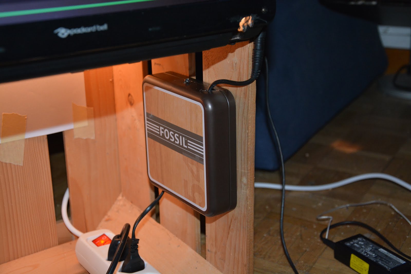
The laptop has a loooong cable which does look ugly if it is "just in the box". Luckily, our local jewelry store keeps the jewelry boxes from Fossil (http://fossil.com), which I get from time to time for free. I already built two RasPis into such boxes, they are very nice.

I had a box left where the cable just fits in. I made two holes for the cable on the side, two holes for the screws in the back and another hole into the top side to fix it with a screw when it is assembled.


Then I made a light into the box. Just a standard light fixed on a tobbacco box and with a switch, no big deal. To not press the (functioning ;) ) keys, I fixed the light on a cardboard which fits exactly in the box, cut out a tiny bit for the cable and put it over the laptop.

I put in some standard white A4 paper into the inside of the box to cover the free spaces.
It was way to bright.  I thought the screen on the front side would swallow the light, but it doesn't.


Luckily (again), I had an old duvet cover left in a nice green color.

I moved all the stuff out of the box and used a staple gun to put the fabric inside. The cable box was then assembled to the box again with the fabric between. WARNING: Use an "industrial" staple gun (for wood), not a standard bureau staple gun. I needed about 20 staples until ONE got in right, for every one. Later I borrowed the right staple gun from a friend...


The fabric must cover all the holes on the top of the box. The light will shine through the smallest hole, so cover it. ;)

(I show the image of the light just here and not above, because there is no image with the light and no fabric.)

I made a front cover out of fabric for behind the screen, built in 3 (three) magnets on each side and stapled the top side to the top (inside) of the box. I used some metal pins (standard bureau pins) in the box for the magnets to hold on.


A friend got me a flat USB-hub with a flat cable. I got rid of the plastic housing and made a cigarillo-box housing for it. Just put the hub between some paper to shield it from the housing metal.
That  is the only thing which I glued to the box.


At the very end, I needed to attach some wheels. I turn that thing every now and then, it needs wheels...a wheel is Fr. 6.50 at Schwab Eisenwaren (my local metalware store), a little bit expensive but worth it.


Last but not least, there is a standard power strip. I cut the cable to make the hole in the fabric as small as possible, and connected it again together on the outside of the box.

The laptop should have WiFi but no Bluetooth is needed because the audio cable fixes the laptop on the box anyway. So, why not use it? (This model does not have BT, either.)

[EDIT: 2016-11-11]: Some key was pressed all the time from the broken keyboard. I ripped the whole thing off. Luckily, the power button has its own cable. I glued it to the side of the box.

The button is the small metal thingy above the cable strip.
The big glowing thingy is just the power LED.
I thought about putting a hi-fi system under the laptop, but this is something for another time.

I use it for:
+ Putting stuff on it.
+ Listening to music (Spotify, Youtube)
+ Watching TV with a decent background light. (On a real TV, not this little screen.)
+ Playing Endless Sky and Minecraft Classic on my own server "Super Ben0bi World".
+ Da Interweb, google and stuff... ;)
+ Zonk out with a decent background light and decent background music. ;)

I hope you like it. I hope you build your own one. Look how it glows...


I cannot live without it anymore. :)
Screen turns off after 2 minutes and the computer goes to sleep after 2 hours. I need long to fall asleep...


Update, Version 1.1

December 2016 (Written: 1.1.2017)

I really use that thing. Did not think about that. :) In fact, I love it, it is the second most used computer in my home.

I added some stuff. There is now an "internal" USB-extender with some cables for smartphones and stuff, and a card reader, which is also "internal". I exchanged the bulb for a LED-bulb because this will not break so fast. On the top is now a layer of transparent black plastic foil to cover the internals from...coffee. ;)

Also, I found a wonderful LoFi-System (It's not Hi, you know, it's cheap.), which fits EXACTLY into the box. It is a "SilverCrest SMBC 30 A1", and "can" Bluetooth, 1xAUX, FM-Radio, CD and USB. It is also delivered with a remote. Can say nothing for just 99CHF. Other stores would only sell the front plate for 99.-... XD

On the product photos, the LED-display is "cheap-red" but in original it is in "soft-nice-orange" and can be dimmed in 4 steps inclusive turnig it off.

Photos:

The card reader is fixed with fabric on the side.

The Fossil-box is not gone, it is now under the music box

The internal USB is connected to the external one on the bottom side.


Thanks for your attention. Please like. Please comment. Please follow this channel....wait, this is not youtube nor facebook...lucky me... :)

Dienstag, 12. Juli 2016

jQuery (+Twig) Tricks: Parameter Mayhem

So, you want to call your JS function out of a link, but it has so many parameters that you cannot see the forest out of trees?

I found out this little trick to "externalize" the parameters of my functions in the link.

For this one, jQuery is required. I do not explain here how to use jQuery.

Example Function ("Wrong"):
function myFunction(param1, param2, param3)
{
  ... do something with param1, param2 and param3
}

And this is the example link:
<a href="#" onclick="myFunction('text', 2, 'anothertext');">go</a>

With Twig it would look like this:
<a href="#" onclick="myFunction('{{ twigparam1 }}', {{ twigparam2 }}, '{{ twigparam3 }}');">go</a>

I do not want to use an event-trigger because the page must be built up to register the event on some elements. (e.g. $("div").click())
If you build another div after this event was registered, this new div will not trigger the event, except you register the event again. That is, why I use functions directly in the link. It's not good practice, but on the other side, we don't have to care, where and when our events have to be registered or not.

If you have more and more parameters, this will look uglier and uglier and you cannot see where this " starts and this ' ends. ;)

Fortunately, we can add data to the link with the data-xxx parameters:
<a href="#" onclick="myFunction()" data-param1="text" data-param2="2" data-param3="anothertext">go</a>

You can add as many data as you want, just use the prefix data- and your desired parameter name.

In the function below, you will see how to get this data. But first we need to give the link itself to the function, so it can get the data out of the link. For that we just use $(this) from jQuery as function parameter in the link:
<a href="#" onclick="myFunction($(this))" data-param1="text" data-param2="2" data-param3="anothertext">go</a>

And with Twig it would look like this:
<a href="#" onclick="myFunction($(this))" data-param1="{{ twigparam1 }}" data-param2="{{ twigparam2 }}" data-param3="{{ twigparam3 }}">go</a>

All we need to do now, is rewrite our function to use the data from the link:
function myFunction(link)
{
   var param1 = link.data("param1");
   var param2 = link.data("param2");
   var param3 = link.data("param3");

  ... do something with param1, param2 and param3
}

Hope that helps.

Mittwoch, 4. November 2015

GAMEBOY Devkit ben0bi Edition

I downloaded the Gameboy devkit and played around with it like here.
In the developing process, there were some stuff downloaded which I included in the original devkit.

Here are the downloads:
gbdk_ben0biEdition.zip from Mirror 1 (Onedrive)
gbdk_ben0biEdition.zip from Mirror 2 (Homeserver)

And here is what you get for it (copied from README.txt):

First of all, you need to call do.path in every new terminal window, else the paths are not defined. Call it like that: . do.path in your gbdk-root directory. (NOT ./do.path)

Please look also at this post, my friend SneezyCerritus got all out of an old Gameboy Color.


Additions:
+ gbdk-doc downloaded from sourceforge.net (If you can redeem 8.8Mb for the Nintendo Manual,  you can do that with this 50kb for sure.)

+ A shell script to set the path for GBDKDIR. Please change this to your own path.
    + do.path ->    Call it with: ". do.path" because "./do.path" will not
            set the variable globally.

+ RGBDS (compiled and source) for fixing the code to run on real GameBoy hardware.

+ Some PDF-resource.
    + GBCPUman.pdf             -> GameBoy CPU Manual by some people from the internet.
                        This one contains some tips and tricks.
    + gb_programming_manual.pdf    -> Original document by Nintendo.
                        I have no idea where I found this.
                        Biggest file of the whole compilation. ;)

+ A tile editor for LibreOffice: assets/ben0bis_GB_TileEditor.
    + And a font created with it, spread over several files in the assets/new folder.
    + Also as zip-file if you do something wrong.

+ New code from myself in the ben0bi-folder with some shell-scripts to automate.
    + ben0bi/credits    -> Credits of this whole project.     (Not finished yet)
    + ben0bi/IRremote    -> An IR remote for your TV.         (Not finished yet)

+ Some shell scripts from myself and updated Makefiles to use with libraries. (multiple .o-files)
    Look in the subfolders of the ben0bi-folder:
    + Makefile    -> the original one from the examples does not work properly.
    + do.all    -> calls all the other do-files and starts the game after compiling.
                It uses VisualBoy Advance (vba) as emulator, please install it.
    + do.compile     -> calls "make clean" and then "make"
    + do.fix    -> fixes the file to use on real GameBoy-Hardware.

        You need to set the proper filename/s in all of this files.


+ New Examples, stolen from the internet:
    + examples/burlyGBC_src    ->    a little game where you are a bear.
                I learned how to use graphics with that one.
                Contains the original tile editor tiles17.xlsx
    + examples/IR        ->    contains some source to use the IR sensor.
                (code not used yet.)

Samstag, 29. August 2015

GameBoy Color: Hardware Modding

Like mentioned in this post here, my friend SneezyCerritus gets the best out of an old GameBoy Color on the hardware side. I wanted to load my homebrew GBC-modules so he ordered a cardridge with a microSD-slot. Then he had the idea to put that cardridge inside the GBC so we could either use games from the microSD slot (all there are ;) ) or use an original Gameboy-cardridge on the other side, without taking the microSD-cardridge out.

Also, he decided to put an accumulator pack and a microUSB-accumulator-load-slot into it.

WARNING: This project is freaking expensive and only for enthusiasts. It is a nice thing but it's very costly. I bet you can never sell it for the price below, which is:
--> more than 300 CHF and counting...

This is the device we are talking about, in exactly that color (but this images are stolen from the internet because we started making pictures after the start of modding.)


And here is an image of the back, for your consideration:


Here is what we got to build into the case:
http://opcoa.st/JGdT7

It's an "Everdrive GB V1.2"

Also he got a Li-Ion-Accumulator-pack, a loading-chipset hardware breakout and a miniUSB-plug.

Accumulator, USB-and-loader-breakout and Everdrive.

First a view from the workplace: In front you see a not-yet-functional 3D-printer (software issues). The GameBoy workplace is just beneath it, you cannot see it.
Workplace
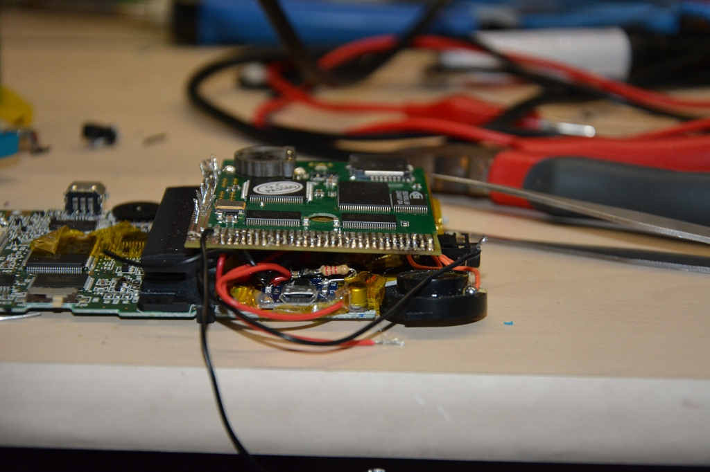
Here you see all the parts, on the backside is a cutout because there were not enough space.
All the needed parts.

Ok, first he opened that the GBC and the Everdrive. For the GameBoy you need a special screwdriver with three 3 "corners". (NOT a triangle! It's like a normal screwdriver but...triple.)

He soldered a cable to each pin of the GameBoy-hardware and put in the Accumulator and loading-stuff.
First try with cables.

Soldering the cables together.

After that he soldered it to the Everdrive and tried to close the case.
All done, does it fit?

It's not possible, so he unsoldered the Everdrive and made a special PCB only to connect the two pieces together.
PCB for the second try.
That glassy thing is a selfmade PCB-creator. It's just some ultraviolett LEDs and a glass plate and some covering, I don't know how it works exactly.

He then cut the wires short and soldered the PCB on the GBC and the Everdrive on the PCB.
 
PCB, GBC and Everdrive soldered together.

PCB sideview.

Problem is, it will not fit to the case either. The case needs to be extended, with some parts changed.

SneezyCerritus used some 2-component superglue to create the outer shell of the expansion on the original case. Then another friend removed the inner parts, until only the superglue-case was left.
Some glue on the right place...

..makes the shell bigger.

Getting rid of the stuff inside.
When you fail in this (there was a hole where no hole should be), you can use some more glue to fix it, easy. The battery case cannot be opened anymore so the accumulator is necessary from now on.

He put it all together but it won't fit either. The PCB was to big.

The last solution for that issue (which finally worked) was to take a ribbon cable like on that image here:
 

Here you see an image from the de-soldering process, with the ribbon cable in the background.
De-soldering the PCB.

After that, soldering the stuff to the ribbon cable:
Nice view with ribbon cable.

Third and last soldering process. :)

Two LEDs were included into the case to indicate if the battery is charging or fully loaded:
Loading LEDs.

After reassembling, the working test...it works:


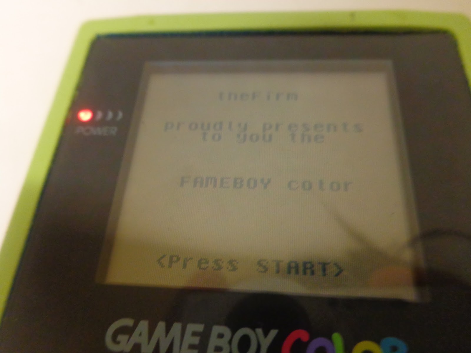
Do you like the color? I do.

It is now possible to use the internal microSD-card OR an original cardridge. You can even take out the microSD-card without opening the whole case. It's not very beautiful but it makes its job.

microSD-card slot.
Switch for cardridge-or-microSD-operation.
microUSB-slot for charging battery.
And finally, homebrew software running on the "original" device:
Homebrew Software. YAY!

That's it, all is working like it should. This project lasted over several months.

Sorry for the long post, I hope you enjoyed it.